Hey everyone, thanks for dropping by my blog—if you’re here, chances are you’re either designing a power supply circuit, troubleshooting a wonky flyback transformer that’s been frying your boards, or you just want to make sure your next transformer build doesn’t end up costing you a fortune in replacements. I’ve been supplying flyback transformers for over 12 years now, and I can’t tell you how often people reach out saying, “My unit keeps blowing up—what did I do wrong?” Nine times out of 10, it’s not a bad transformer; it’s that the protection mechanisms around the transformer are either missing, misconfigured, or they’re not actually set up to handle the abuse flybacks take. Let’s break this down like we’re chatting over a coffee, no super-jargon-heavy textbook nonsense—just the stuff that actually matters when you’re relying on a flyback to work. Flyback Transformer
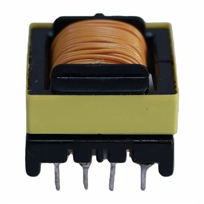
First, let’s get one thing straight: a flyback transformer isn’t just a coil of wire wrapped around a core. It’s a little power house that stores energy in its primary winding when the switch (usually a MOSFET) turns on, then dumps that energy into the secondary when the switch turns off. That back-and-forth is why it’s so efficient for low-to-medium power apps—think chargers, small LCD displays, compact power adapters, even some industrial control modules. But that energy dump? It’s volatile. No wonder protection is non-negotiable. Let’s start with the most critical one I see people skip: overcurrent protection (OCP).
Wait, I’m not just talking about a basic fuse here. Fuses are a last line of defense, right? They blow once, and you have to replace them. For a lot of designs, especially ones that cycle a lot, you need active OCP too. Active OCP uses a current sense resistor in series with the primary winding, or sometimes a current transformer clamp, to monitor how much current the primary is drawing. If it spikes past the threshold you set (usually a little higher than your normal operating current, so you don’t trigger it accidentally when the load surges), it tells the MOSFET to turn off early, before the current gets high enough to melt the winding insulation or fry the switch. I’ve seen customers come to me with transformers that had 10A primaries running at 15A, because they skipped active OCP and relied on a 20A fuse. The transformer would get so hot, the insulation between windings would break down, and suddenly you’ve got a shorted primary and secondary. Active OCP is like a bouncer at the door—if someone tries to cut the line (or in this case, draw too much current), they get turned away before they cause damage. And for the record, when you’re selecting a sense resistor, don’t cheap out on its power rating. A 0805 resistor rated for 1/8W might work, but if your current surges, it’ll burn out and suddenly your OCP is gone. I always recommend a 1/4W or larger, just to be safe.
Next up, overvoltage protection (OVP). This one’s a close cousin to OCP, but it’s focused on the secondary side. Let’s say you’re powering a 12V device, but something goes wrong—like the load disconnects, or the MOSFET fails to turn off, and the secondary voltage spikes way above 12V. That’s a big problem because your delicate electronics (microcontrollers, sensors, whatever’s on the other end) can’t handle 20V or 30V. The two most common OVP methods we see are a zener diode on the secondary, and a crowbar circuit. The zener is simple: you pick a zener voltage a little higher than your nominal output, so if the voltage goes above that, the zener breaks down and shunts excess current away from the load. The crowbar is more aggressive—it’s a thyristor that triggers when voltage spikes, and basically shorts the output to ground, which blows a fuse before the transformer or downstream gear gets damaged. But here’s the mistake people make: they set the OVP threshold too close to their operating voltage. If your load has a sudden surge, like when a motor kicks on, that surge might nudge the voltage just enough to trigger OVP unnecessarily, which can shut down the whole system. I usually tell customers to set OVP at 15-20% above their nominal output—enough to handle surges, not so high that it’s useless. Also, don’t put the zener directly across the secondary winding without a current limiting resistor. I’ve seen that zener burn out in 10 minutes because there was nothing stopping the high secondary current from flowing through it.
Now, let’s talk about the transformer’s own internal insulation and material protection—something a lot of people don’t consider, because they think the transformer itself is just a passive part. But when you’re working with flybacks, especially ones that run at high frequencies (like 60kHz to 100kHz, which is standard for most compact designs), the windings heat up, and the insulation between them has to hold. I always use transformers with a Class B or Class F insulation rating, but even then, you need to make sure there’s enough creepage distance between primary and secondary. Creepage is the physical distance between two conductive parts, right? If the distance is too small, high voltage can arc across it, especially when the transformer’s hot. For low-voltage apps (up to 24V), 0.5mm is enough, but for higher voltages (like 48V or more), go with 1mm minimum. Also, the core material matters—we use high-quality ferrite cores, but even ferrites can crack if they’re subjected to too much vibration or temperature swings. We pot some transformers in epoxy for industrial apps, and that not only stabilizes the core but also adds a layer of insulation, which is an extra protection. I had a customer last year who was mounting transformers in a machine that vibrated nonstop; their original transformer had a core that cracked in 3 months, leading to a short. Switched to our potted versions, and they haven’t had an issue since.
Wait, let’s not forget thermal protection. Flyback transformers run hot—no way around it. The copper windings have I²R losses, the core has hysteresis and eddy current losses, and if that heat builds up, it can degrade the insulation over time, leading to premature failure. The best way to protect against this is a combination of good design and, if needed, a thermal fuse or thermistor. A thermal fuse is a one-time use thing, great for if the transformer gets too hot (say, if the OCP fails and current keeps spiking), it blows and disconnects the transformer before it catches fire. A thermistor is active—it changes resistance with temperature, and can trigger a shutdown in the control circuit if the transformer gets too warm. I recommend a thermistor for most consumer and commercial designs, because a thermal fuse means you have to replace the transformer every time it overheats, which adds downtime and cost. Also, when you’re laying out your PCB, give the transformer some breathing room. Don’t crowd it with other components, especially big ones that trap heat. Leave at least a 5mm gap around it, and if you can, add a small copper pad on the PCB under the transformer to act as a heat sink. That simple change reduced transformer failures for one of my clients by 40%—they were just cramming everything onto a tiny board before.
Another big one that’s often overlooked: short-circuit protection (SCP). A short circuit on the secondary is one of the worst things for a flyback. If the output is shorted, the transformer keeps dumping energy into the short, which makes current spike way higher than OCP’s threshold, and if your OCP doesn’t catch it fast enough, you’re looking at a shorted winding or a blown MOSFET. A lot of active OCP circuits have built-in SCP, but sometimes it’s not aggressive enough. You can add a current limiting circuit on the secondary, like a small inductor in series with the output, to slow down the current spike during a short. Or, for AC-driven flybacks (wait, no, most are DC-DC now, but some are line-powered), you can use a slow-blow fuse instead of a fast-blow. Wait, no—wait, a slow-blow is better for inrush current, but for a short, you need something that responds fast. I always recommend a PTC (positive temperature coefficient) resistor on the secondary for SCP. A PTC stays at low resistance when current is normal, but if a short happens, it heats up and its resistance jumps, limiting the current so the OCP can do its job. It’s reusable, too—once the short is fixed, it cools down and goes back to normal. That’s way better than a regular fuse, which is a one-and-done.
Wait, let’s circle back to the transformer itself, because as a supplier, I can tell you that even the best protection mechanisms won’t save a cheaply made transformer. A lot of no-name transformers cut corners on winding gauge, insulation, or core material, and they fail even when all the external circuits are perfect. That’s why when you’re sourcing flyback transformers, don’t just go for the lowest price. Ask about their insulation rating, creepage distance, core material, and testing procedures. We test every transformer we ship for 24 hours under full load, and we do a dielectric strength test (hi-pot test) to make sure there’s no arcing between primary and secondary. If a supplier can’t tell you what their protection specs are for the transformer itself, or won’t show you their test reports, keep looking. I’ve had a customer bring me a transformer from another supplier that failed a hi-pot test after only a week—turns out they used insulation that was rated for half the voltage the transformer was supposed to handle.
Oh, and let’s talk about Emi protection? Wait, is that a protection mechanism? Maybe more of a mitigation, but it ties into longevity. Flybacks generate a lot of electromagnetic interference, which can interfere with other circuits, but also, if not shielded, the interference can feed back into the control circuit and cause the MOSFET to switch erratically, which leads to current spikes and failure. We offer shielded flyback transformers, which have a copper shield between the primary and secondary windings that contains the EMI. It doesn’t just make your design comply with FCC or CE standards—it also keeps your transformer running smoothly, because erratic switching means no big current spikes. That’s a win-win.
Let me give you a real example to drive this home. A few months ago, a guy reached out to me, frustrated because his company’s portable LED lights were failing after 6 months of use. Each light used a 12V flyback transformer to power the LED array. His original design had no active OCP, a zener on the secondary, and a regular fuse. The problem? When the LED array would short out (they’re fragile, especially if dropped), the fuse would take too long to blow, and the transformer would overheat, melting the insulation on the windings. He was replacing 20% of the lights every month, which was killing his profit. I recommended he add active OCP with a current sense resistor, swap the regular fuse for a PTC resistor, and switch to our Class F insulated, shielded transformers. Within a month, his failure rate dropped to less than 1%. That’s the difference between just slapping a transformer into a design and actually setting up proper protection.
Wait, what about under voltage protection (UVP)? Yeah, that’s another one—especially for devices that run on batteries. If the input voltage drops too low, the transformer might not be able to regulate the output, leading to unstable power that can damage the load. UVP monitors the input voltage, and if it goes below a threshold (like 90% of the nominal input), it shuts down the converter so the transformer doesn’t run inefficiently or draw excessive current. That’s super important for battery-powered apps, because running a transformer at too low an input voltage wastes battery life and shortens the transformer’s lifespan.
Let’s wrap this up with a quick checklist, so you don’t forget anything: 1) Active OCP + a current limiting fuse/PTC to stop primary current spikes, 2) OVP on the secondary set 15-20% above nominal output, 3) Good insulation and creepage distance on the transformer, 4) Thermal protection (thermistor or thermal fuse) to prevent overheating, 5) SCP to handle secondary shorts, 6) A shielded transformer to reduce EMI and erratic switching. None of these are optional—skip any, and you’re asking for failures, downtime, and extra costs.

Now, if you’re designing a new power supply, troubleshooting a failing transformer, or you need flyback transformers that are built with all these protection mechanisms (we make sure every unit leaves our shop with the internal insulation and testing to back it up), feel free to reach out. I’m always happy to walk through your design, suggest the right transformer, or help you tweak your protection circuits to make your system rock solid. We don’t do one-size-fits-all here—we work with each customer to match the transformer and protection setup to their specific needs, whether it’s a small consumer adapter or a rugged industrial module.
High-voltage Transformer References:
- Mohan, N., Undeland, T. M., & Robbins, W. P. (2003). Power Electronics: Converters, Applications, and Design (3rd ed.). John Wiley & Sons.
- Texas Instruments. (2021). “Flyback Converter Protection Circuits” Application Report.
- Fairchild Semiconductor. (2019). “Designing Reliable Flyback Transformers for Power Supply Applications” Technical Brief.
- International Electrotechnical Commission (IEC 61558-2-16). Safety of power transformers, reactors and their associated assemblies – Part 2-16: Particular requirements for flyback transformers.
Dongguan Hensiron Electric Co., Ltd.
As one of the most professional flyback transformer suppliers in China, we have world-leading production equipment and strong manufacturing capabilities. Please feel free to buy high quality flyback transformer made in China here from our factory. Customized orders are welcome.
Address: Building 4, Xinxing Industrial Zone, Wangao Road, Wanjiang Street, Dongguan City, China
E-mail: jessica@dghensiron.com
WebSite: https://www.dghensiron.com/
